
Rotary Snow Train
I am jumping in on a major project, my long dreamed of rotary snow train. This will consist of at least 10 items.
These will be:
Rotary CY – A Leslie Brothers style steam rotary built sometime in the mid 1920s. It will have features from D&RGW OM, OY and ON. Prototype research is located here; Rotary OM & OY – Research Notes
Rotary CY Water Car – A modified framed tank car
Engine 51 – A K27 from the Accucraft line. This the power for moving the entire train.
Engine 50 – A K27 from the Bachmann Spectrum line. This will be a dummy with the motor removed to allow free wheeling of the drivers.
Engine (currently undesignated) – A K27 from the Bachmann Spectrum line. Another dummy with the motor removed to allow free wheeling of the drivers.
Tool Car (currently undesignated) – A 30′ wood side boxcar.
Bunk Car (currently undesignated) – A modified 30′ wood side boxcar.
Cook Car (currently undesignated) – A modified 30′ wood side boxcar.
Engine-men’s Car (currently undesignated) – A modified Jackson and Sharp Combine.
Caboose 501 – A center cupola short caboose.
Rotary CY
Several years ago my friend Richard “Ski” Kozlowski designed a kit to turn a RTR wood side boxcar into a D&RGW rotary style snow plow. It closely resembles OY, especially the rotor-head. This was printed as multiple parts on a 3D printer in both 1/22.5 and 1/20.3 scale. He built the model for his RR in 1/22.5 based on a Bachmann Big Hauler boxcar and gave me the other kit.
The Idea was to produce a better looking model than the USA Trains Rotary (1/29th scale) and more affordable than the craftsman kit from Grizzly Mountain Engineering (1/20.3 scale). Modelers could cut a few holes in a RTR boxcar then attach the components with screws or glue as required. All that would be left was to modify a tender. Ski used a Delton tender in 1/24th scale for his version. I am not going to cover its construction but here is a final picture. I think it looks great.
For my build I am using a Bachmann Spectrum boxcar for the rotary unit and a tender from a 4-6-0 Big Hauler. I have run into problems immediately because I am not using the kit the way it was designed. After seeing the GME kit completed on a friends layout I must at least try to come close to it. It is a thing of beauty that only a narrow gauge nerd could love but I cannot afford it. Keep that in mind as I go through this build. It is not Ski’s kit but my own anal-tivity that causes the problems.
Rotary Unit Construction
Here are all the components:

This is a 1/20.3 model (all be it freelanced) but the Leslie Rotaries were all built as standard gauge equipment. If you have ever been to Chama and seen OY or OM you know how large they are. Even though I am not building a model of any of the D&RGW units I still want that massive look. The kit components are also printed in 1/20.3. You can see below how this is crowding the build. Here is Greenman in comparison to the doors, shroud and boxcar.


This is where I first considered switching to scratch-building the basic body but at this point I was still trying to prove the kit design. If I knew then what I know now I would have. But onward. Time to dismantle the car and get out the razor saw. Disassembly is covered here: Rolling Stock Disassembly Instructions
After taking the car apart I marked off the window and door positions and started cutting.These are almost all inside cuts so I used the back edge of the saw to carefully make the cuts. I held it at a 45 degree angle and pulled it gently backwards drawing a small kerf of plastic out of the cut line. This is tedious but it keeps the surrounding area free of stray cuts and scrapes.

The last cut was for the I-beams that support the tension rod. All of the prototypes have the first support at the front right behind the rotor shroud. OY has the second one just behind the engineers door. OM and ON both have the second support behind the crew door.


Having the tension rod at the back made the kit fit better so I chose that placement.

You may notice the angle on the rear of the unit. All of the rotaries have a partial enclosure to shield the fireman from falling debris and flying snow. OY has a cut out reminiscent of a passenger car. OM has the rear angled as shown. Ski’s kit comes with the two pieces to make this but I figured why cut the back off just to glue the same sort of thing back on.


Now I needed to make a decision on the frame. I had intended to use the one that came with the boxcar but then noticed that all of the rotaries sit on metal frames that extend below the wood sheathing. It was an opportunity to make up some of the missing height on the build. I knew I could not do much about the width without completely cutting the boxcar to pieces but I could effect the height. I decided on a 1″ thick piece of polystyrene for the frame. No one would see the underneath and it would give some much needed weight as well. Using the 1″ polystyrene added a 1/2″ to the cars height (the sheathing on the model comes 1/2″ below the floor). First I cut out all of the supports under the car and glued the block in place with E3K. With so much surface contact I decided screws were not needed.


For the top I glued 1/4″ polystyrene bar and then added a cover of bass wood. The odd little pieces where the door was were filled with polystyrene as well. A little sanding and I had gained a 1/4″ at the top. My project was now noticeably higher than it’s boxcar brethren. With a rounded roof it would look even taller.


I glued in the rear wall next. Some tongue and groove sheathing will be added for the inside walls and roof.

Originally I was not going to do an interior but after looking at it and thinking how nice it would be to have interior lights and a crew I changed my mind. A did settle on a basic interior though no super detailing. The inside walls were made from matte board embossed to look like tongue and groove siding. I measured the height I needed for the walls and marked that on a piece of matte board. Then a few reference lines were added so my scribes would not lay over sideways as I moved across the section. Using a metal bar I pulled the blunt edge of a #2 flat blade screw driver across the matte board with firm pressure.


Once I had done the entire panel I cut it off and then cut lengths as needed. By holding the piece up to the inside of the wall I could mark where the window openings were needed. These were cutout using a Exact-o knife. I glued the pieces in with E3K and once dry the edges were sanded flush.
With the inside walls done I could move back to the exterior. Time to put that “off- cut” from the end to use. I marked off sections to fill in on either side of the doors. They were carefully fitted into the openings to line up with the grooves in the siding siding. A note for a Bachmann oddity here. The sidewalls of the Spectrum boxcar taper from thick at the bottom to narrow at the top. Because of this I had some trouble getting the boards to sit in the hole properly.


To hide the joint I used Milliput two part epoxy filler. The wood grain was faked by dragging a razor saw along the boards. The groove was sculpted in with a small screw driver. Once dry it was lightly sanded to smooth the joint.


There was not enough of the off-cut left to fill the entire space but the access doors will cover the opening. I glued in a section of matte board to level it up.
Now I can fit the roof and set the front windows. The roof has to be removable so I can install the interior. It cannot be screwed on because the heads would show. Neither can it be glued on as I need to be able to change the batteries and get to the lights. A friction fit is needed. Details along the roof line prevent it from overlapping to the exterior side like most coaches are done. It has to have a channel inside.
I cut bows from double tempered hardboard using a quilting guide. These were taped together with one small drop of glue in the middle to keep them from shifting while sanding.


The ends are part of the removable section. They were finished to match the front and back as needed.


A quick look at how the rotor will sit.

With cold wet weather I forecast for the next week I felt it was a good time to work details. I glued on the access doors based on OM but with the details of OY.


Altogether there are 124 rivets, 25 grab irons / steps, 5 chain anchors and 2 door knobs per side totaling 181 holes to drill. Binge watched a lot of Netflix during that time.


I was able to use most of the grab irons from the boxcar but had to make some out of steel floral stem wire. It bends sharper than brass and is much cheaper. It does not solder very well. The rivets are made from HO track spikes (atlas #2540 round heads). All most all of those had to be cut short as only the ones in the access doors could penetrate the walls. Those will be covered by the interior walkway over the cross-head. The door knobs are brass furniture tacks.
While the body is sitting upside waiting for glue to dry I made a simple set of bolsters out of polystyrene. A center line was located and did some guessing on where the trucks to sit without hitting the ash-pan or causing to much end swing. Ski had complained that his model had issues with this because the rear truck is so far forward. I am lucky to have large 20′ diameter curves so I hope I have allowed for the spacing between the rotary and tender.


Truck time. The plan called for using the boxcar trucks as is. After looking at the Fox pressed steel trucks on OY I decided I could make a pretty good facsimile. Not wanting to cut the Spectrum trucks up I pulled a set of Bachmann Big Hauler trucks out of the junk box. They are close enough in size and the Spectrum wheels sets have plenty of clearance.

My idea is to make a cover that will look like the Fox trucks. The basic truck will be hidden behind it and none of the original geometry will change.


The ends and molded springs were cut off on the band saw while the cover plates were taped together and sanded to shape.

The plates are designed to slide down from the top leaving the journals protruding through. The back of the journal bolts had to be cut and sanded to make room. Once in place the top and bottom edge was sanded flush. Thin styrene strips were glued along the top to make the L channel. Some square styrene stock was glued down the ends behind the plate to hide the original truck. Finally some thin strips were added below the journals.


The styrene strips were trimmed and sanded flush. After looking at the rivet pattern on the prototype I decided to go for a representative number of rivets rather than actual. I still ended up with 65 rivets, 4 bolt-heads and 2 chain anchor holes per truck.
The rivets are Atlas HO round head track spikes #2540. All of them had to be clipped to 1/8″ so they would not protrude through the truck frame. The bolt-heads are end cuts trimmed from styrene rod. After the glue dried I sanded them down to the correct height. The anchor holes are for the chains. I plan on using small cotter keys and jewelry chain but I cannot put these on until everything is painted.

Reassembled. I think once they are painted the trucks will look pretty good. Now the trucks could be attached until paint time.

With the trucks screwed on I marked off the space for the ashpan and put together a simple box. It is hardly seen but I did make the frame for a sliding door and mechanism to operate it.
The snow plow is based mostly on the one under OM. It is a angled blade with a curved section at the top. I mounted it using a piece of rod as none of the prototype linkage would be visible.
")
")
It is all styrene except the curve which is cut from a cheapy ink pen.

View from the bottom with all the pieces in place. Still need to find a brake cylinder and connect all of the chains.

And of course the current state of the model sitting upright.

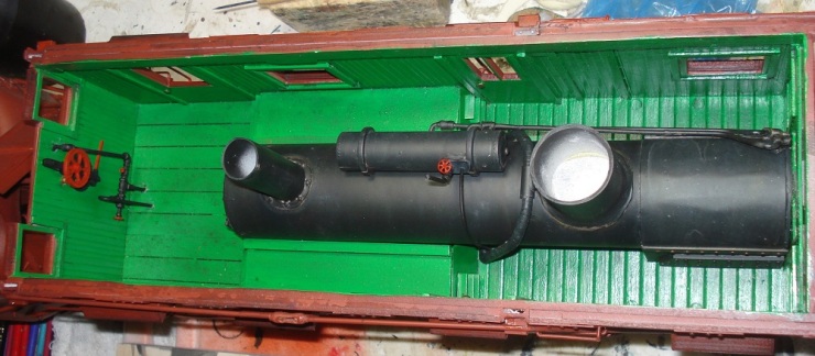
Constructing The Interior
The interiors for both OM and OY are similar. The boiler sits slightly above floor level with the firebox and ash-pan passing through the floor. The back-head penetrates the rear wall to give the fireman access from his enclosure. On a normal steam engine the cross-head and cylinders would sit under the smoke box with the drive rods extending rearward toward the drive wheels. Since the steam engines purpose is to drive the rotor head (movement is supplied by the pusher locomotives) the cross-head is moved back with the rods extending forward to a gear mechanism under the engineers floor. That mechanism converts the back and forth of the rods to circular motion spinning the rotor. To keep the crew safe from the rods, walkways are built over the top. This makes the area rather cramped. The conversion mechanism is much smaller so the lower floor covers it at the front of the unit.
In the pictures below you can see the walkways I described. The steps next to the crew door are very steep and in OM are in fact just metal foot plates.


The cab for the engineer is pretty spacious, all it has is a set of valves for speed and controls for reversing the direction of the rotor. There are also valves for the de-icer steam lines and a large wheel for switching the direction of the ejection chute.
Seating is pretty plain. Two wooden pedestals with a pad and no backrest.

I will build the steam lines out of brass rod. The chute mechanism is the brake wheel off the boxcar and some gears from Hobby Lobby. The rest of the interior is framing for the doors and windows.

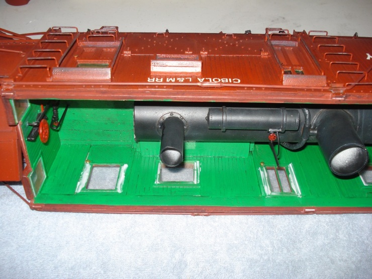
Detailing the boiler.
The boiler has all of its guts up on top so the crew get to them. I am not going to fully reproduce this but will instead put in a few basic lines and the larger components.

The boiler is made from PVC pipe with sheet styrene forming the fire box. Rivets are once again the HO round head track spikes.

The air tank and piping is salvaged from a Bachmann 4-6-0. The high pressure steam lines are styrene tube bent and wrapped with masking tape to mimic the insulation. To keep it from drying out and falling off I gave it a coat of glue as sealer.


The interior. The boiler will get glued in and the rest of the details added after everything is painted.

Constructing The Roof
To cover the roof I used 1/64th birch plywood. It is very strong, flexible and can be cut easily with a good pair of scissors. To get it on the ribs I glued one side and let it dry then folded it over and glued the other side. Once it was dry I trimmed the edges as needed and then went back and glued along all the joints.


I measured and cut out the locations for everything that penetrates the roof. None of the features connect to the boiler but they are centered in the right spots. Those areas can only be scene if you hold the unit upside down and look at the underside of the roof. Not worth the extra frustration of trying to make them connect.
Cutting the birch plywood was a bit fussy. I ended up using an Exacto blade and scoring the lines repeatedly until it broke through. From there I was able to gently cut the remaining material. Once the cutout was gone I sanded the holes for the perfect fit.

Like the rest of the build I took elements from both OM and OY.


Some items were glued in place while others were left loose and will be attached after the roof covering is done.

Depending on where in the life of the snow plows you look they had different roofing material. I think they both began with wood and OY may have had flat metal sheeting at one point in its life. Currently OM has what looks like rolled tar paper nailed over it.


I debated using thin styrene for metal but finally decided that canvas and dope or tar would have been a common choice. To reflect this I found un-embroidered paper towel and cut it into strips. The roof was coated with Elmer’s glue full strength and the paper carefully laid down. I did one strip after another creating an overlap at each section.

After it dried I went back and soaked the towels with a 50 /50 mix of glue and water mopping it on until they were saturated. That took over night to dry. I trimmed the edges and glued on the remaining detail items, running a heavy bead of glue around the base of each one to look like sealer. The grab irons got a dot of super glue. For an undercoat flat black craft paint was brushed on full strength.
The unit was now ready for primer.

As luck would have it the next day was in the mid 50s with just a little wind. Everything was disassembled and a light coat of Krylon grey primer applied. A mile marker of progress has been reached!!! You will excuse me if I take a moment to enjoy it.

The unit looks pretty good in grey and both rotaries were painted that color at different times. They were both red oxide as well. I want a little more color and briefly considered going with Cibola green. In the end red oxide with white lettering won out. Going forward all of my MOW gear will be painted that way.
Full Combat Mode With the Rotor Assembly
Well you can’t have a rotary without a rotor so here is the most dreaded part of the build. Ski had printed the entire head assembly in four pieces. It should have been fairly straight forward to build. The problem was the shroud slipped during printing and the compound curve transition section was off center by 1/4″. He offered to reprint it but did not know when that would be, weeks, months…????

I feel that if I shelve this project now I will loose momentum and it could sit for years. I found these pictures of a model built by Barry Bogs. His solution was to gob the transition area up with modeling putty and sand it to shape. UGH.

Figuring there was nothing to loose by attempting this I took the shroud to the bench sander and removed the offending section. This was a pain, and much less fun than you would think. After a couple of hours and some questionable measurements I had the parts ready. Using a board as a spacer to keep the gap even, I glued in supports at the top and bottom. Once dry these were joined by supports at each bend. So far so good.

To close the gaps, pieces of thin styrene were glued on in quarter sections. I chose to put them on the inside as I thought any irregularities would be less obvious there and it would make sanding the outside easier. The next day I filled the exterior gaps with model putty. This is my old standby Milliput. Once it had hardened overnight I sanded it to shape. This brought the thickness down to about 1/16″. Close to what the original printed wall had been.

All that was needed on the inside was a smooth surface. I used SGP as it is quick sanding compared to the Milliput and I have several tubes of it left from my early figure sculpting attempts. A coat of sanding primer inside and out had the shroud ready for detailing.

The various steel plates and reinforcements are made of white styrene. There are lots of rivets in the shroud. I used HO round head track spikes but this time I could only drill shallow holes. I am proud to say that I only punched all the way through twice. Every rivet had to be trimmed to just a nub and then super glued in place. It was so much easier when I did not have to be concerned with what was on the other side.

For the sacrificial extensions I drilled bolt holes for the locking dogs and then glued the blades in place. Once they were dry I went back and drilled the holes in them. Much easier than trying to drill the holes and hope everything lines up during assembly.
The locking dogs are made by passing a HO track spike from the inside to the exterior. Once in place I trimmed them to length. A small piece of tube is glued around it and a 1/4″ length of square stock attached. To make the ends look more like bolts I filed them flat.

Ready for paint with the ejection chute cover and tension rod temporarily in place.

It had always been the plan that the rotor head would need detailing to represent the hinge mechanism on the blades. Although not exact replicas they would be simple enough. What I had not expected was the ice breakers had printed hollow. They were too fragile to even sand and would have to be replaced.
The blades are detailed using flat styrene strips and uncooked spaghetti noodles. All the parts were glued on with Testor’s model glue and then given a swipe of Plastruc, Plast-Weld solution. Aw glue is glue is glue…by any other name would thou not hold as well? I have a lot of experience with glues but this project has broadened that knowledge, sometimes with frustrating results.


I made new ice breakers based on the style of OY. These are 1/8″ brass bar stock bent and twisted in three sizes using pliers and caveman hands. Once all five sets were made I drilled holes and inserted them in pairs. A few dots of super glue secured them.

Ski designed the rotor head so it could be bolted to a motor shaft for animation. Since I have an interior and no room for a motor I need a center ice breaker cone. OY and OM have different styles. OY is very pointed but flat while OM is more rounded and bulbous. The choice was made based on the fact that I found a wooden craft shape matching OM first. I still included the four prongs found on OY.
A pretty good looking rotor head if I say so myself.

Well that ends construction of the unit. I need to prep it for paint and get started on the tender.
I still need to make the tension rod assembly for each side and the truck chains but those will be part of final assembly. Here is where I am for now.


Letter masked, disassembled and ready for paint. Just need a warm still day.

Constructing the Tender
Like the rotary unit the tender is a compilation of details from both the OM and OY tenders.The prototypes were built from salvaged tenders mounted on heavy steel frames. This gave them the strength to withstand the compression force of the pusher engines as well as getting them to the correct height for the the firemen.
For the CY tender I am going to build it the same way I started the unit. This will keep all of my track clearance and deck heights the same. I actually cut the base and the bolsters at the same time as the unit.
")
")
")


Using a 1″ thick piece of styrene the bolster positions as well as the mounting screws for the tender shell are located and drilled. I moved the front truck back about 3/4 of an inch. This will widen the end swing and help keep it in line with the rear of the unit.

The archbar trucks from the boxcar are put to work on the tender. Bachmann made the spectrum trucks with opening journal covers. You can oil your axles through them. Since they are plastic I find they get broke off and lost to easy. I glue mine down and oil from the rear of the journal.

To smooth out the sides and make the deck look like it is built from two girders I glued on strips of styrene. First a 1″ wide piece using E3K and then two 1/2″ wide pieces using Plastweld. The wood decking is made from coffee stirs.

The rear of the tender deck is a flat piece of styrene with a couple of fake reinforcing strips. I salvaged the step assemble from the original tender deck. The coupler is by Spectrum

Tender Om has a massive piece of wood on the front end. and some pocket steps I think from a caboose.

I went with a block of bass wood and salvaged the steps off of a Piko 0-6-0 switcher. Ground down to sit flat. The steps are glued on with E6K and four track spikes with superglue.

Connecting strips and the next round of a million rivets come next. Pretty good looking deck and very solid.

The tender body is from a Bachmann 4-6-0. I was originally going to use it with as manufactured but the height was wrong and it did not have enough weight. It also lacked that over-built look of the OM and OY tenders.
First the graphics have to go. Bachmann uses stencil ink on most of its products. It can be very difficult to remove. I have had good luck with Scale Coats reusable paint stripper, It took most of the red off. The white proved to be made of kryptonite. I eventually bit the bullet and used the Plastweld for 20 seconds before washing it off and wet sanding the area.
The ink printer must be very hot as found that some of the lettering was melted into the plastic wall. A gob of SGP mixed with a few drops of isopropyl alcohol gave me a paste that could be smoothed over the rivet detail without burying while still filling the indents. Some careful wet sanding finished the job.

A test fit with the approval of the rotary crew.

Rotary snow plows are water pigs. In addition to the tender they all had auxiliary water cars. Water could be brought from these cars to the tender or to the boiler via a pipe on the side of the tender. To make this I bent brass tube for the pipe and flat bar stock for the hangers. The flex joint is heat shrink. Everything is glued together with superglue.
Why no solder it together. Well the tube fits very snug into the hangers. If I have to remove it or adjust how it sits I can pop it out instead of having to remove the entire assembly.

Grab irons made from floral stem wire and a cut lever held on with cotter keys are installed.

A common problem with the 4-6-0 tenders is the plastic grab irons. They are often malformed or missing as they are only pressed into place. The ones on this tender looked okay but they were old and brittle. Since the holes were to big for my stem wire I drilled them to accept 1/8″ styrene rod and glued short pieces in using Testers plastic model cement. This filled the holes and once dry I sanded the ends flat before drilling new holes for the stem wire replacements.

The dog house will not open so all that is needed is a basic shape for support. I started with PVC pipe and some .80 thick styrene sheet. The rest of the supporting structure was made with foam board. To support the doors I used matte board. It is strong and takes porous glue very well.


Once the tender superstructure was covered with wood I made a few details. Here is the double hinge for the doors made from styrene and brass rod.
Construction complete.

Prepped and ready for paint.

Final Assembly
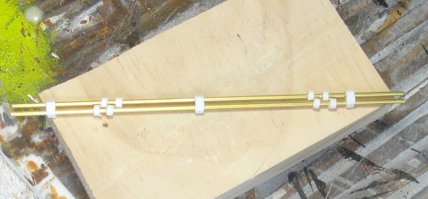
Before I can put everything together I have a few final bits to make. The tension rods are made of .072 brass rod, turnbuckles from Ozark miniatures and washer with hex nuts.
I drilled out the turnbuckles so the rod would slide in. This made the spacing for the bends in the rod a no brainer as the length can be adjusted at the turnbuckle. The rods were bent, measured and cut so the bends lined up over the supports. At first I tried to thread the nuts onto the rods but soon realized I would not be able to get a wrench on them once in place. I opted for washer and nuts that could slide over the rod and be glued in place.

The truck chains are made from jewelry chain using brass wire as the eye-bolt. Holes were drilled in the truck frames and the base of the rotary frame during construction. I measured the chain lengths for the maximum travel of the truck. The wire was bent to form a loop and then slipped onto the last link. The ends of the wire were inserted into the holds and held in place with a dot of super glue. The debris plow was doen the same way.

The push-bar is made from a piece of 1’4 thick nylon strip. Flexible but just about impossible to break. It was attached with a large screw under the ashpan mechanism. I put it as close to the pivot of the rear truck as I could get it in order to reduce the end swing. The other end is a finishing nail. It was inserted at an angle so that it would tend to travel up the pin maintaining the connection. The head of the nail was left on for the same reason.

The fireman’s deck and the overhead cover are made from sheet brass with doll house furniture hinges soldered on. They are attached using HO track spikes as rivets. The spikes pass through the floor and roof and are super glued from the other side.
The windows are made from Acetate cut to fit the interior frame. They are glued in with Elmer’s white glue.
The Crew
Leslie Rotaries were designed for a four man crew. A pilot, a engineer and two firemen. I am modeling my figures as best I can after four of my fellow G scale friends.
Just a few pictures as I have covered this process before in other builds.


There is Ben, Dave, John and Devon. Not bad for a classically trained sculptor and alumni of the Holiday Inn Express, School of Train Repair.

The Completed Model
Left click to enlarge.


I am very happy with the model overall but after five months of construction I am glad to be done with it.

You must be logged in to post a comment.