A Brief History:
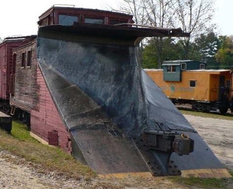
Following the American Civil War railroads of all types boomed across the continent. No longer short lines they spanned great distances connecting not just cities but states and even countries. Keeping the rails open in winter was top priority for the Northern lines as being closed even a few days meant the loss of vast amounts of revenue. For most snow removal jobs a plow on the front of the locomotive or mounted on a dedicated car was sufficient.
A great version, perhaps I will build a model like it someday.
Something more was needed for the deep drifts of the northern tier. Enter J. W. Elliot of Toronto, Canada, a man familiar with snow and the difficulty of moving it. J. W.’s idea was to use a fan shaped head to throw snow out of the way. He never got past the design phase but in 1884 Mr. Orange Jull did. His design was more of an auger but it worked quite well.

Jull sold his patent to two brothers, J. S. and E. who along with M. Sweetnam formed the Rotary Steam Shovel Manufacturing Company in Paterson, New Jersey. I can only guess that going by your initials was all the rage back in the 1880s.
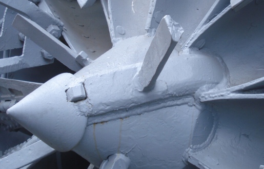
They soon came out with a new design, a rotating cutter head that pulled the snow through fan shaped blades and then used centrifugal force to eject it out to the side.
With an internal mounted steam engine to drive the head the design soon became the standard on railroads across North American.

The Leslie’s contracted out construction of the plows to the Cooke Locomotive and Machine Works. With the D&RGW taking delivery of its first two units in 1889 they were designated Plow #1 and Plow #2. They were both standard gauge units which is the reason they are so large. If you go to Chama and see them in person you will notice the size difference to other equipment immediately. Plow #1 was used on the D&RGW standard guage lines for while but by
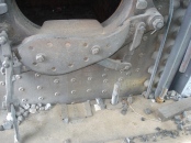
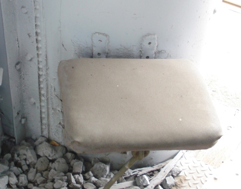
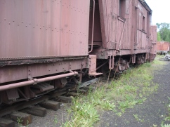
I have grouped the pictures by major component. It is mostly close up shots of the details. I hope these will help modelers who need a few specific questions answered like, how do the paddles attach to the rotor or what does the inside of the tender look like?
Pictures of Rotary OY as of June 2016 (Chama NM)

Body
Shroud

Rotor Assembly
Back-head
Fireman’s Enclosure
Tender
Trucks
Pictures of Rotary OM as of June 2016 (Chama NM)

Body
Shroud
Rotor Assembly
Backhead & Fireman’s Enclosure
Tender
Flanger
Trucks














You must be logged in to post a comment.