When I first installed my layout I was mostly interested in running trains. Knowing that building bridges and refining the scenery would take a great deal of time I elected to use temporary bridges and abutments where needed. In most cases these were 2 X 4s held together with drywall screws. In there defense they have done a good job of supporting my track but it is now time to replace them.
My bridges are not exact models. They look pretty good with sufficient detail and attention to the type of design for the average garden railroad. Mostly I want them to meet this criteria:
1. Durable – I use cedar and pressure treated pine. Conduit or pipe is incorporated inside the frame to prevent warping and sagging. All joints are glued with TB3 and secured with pin nails, ribbed panel nails or drywall screws. In the abutments I frequently use 3″ finishing nails.
2. Simple to build – I am not a rivet counter and lack advanced carpentry skills. If I can build it anybody can. I stick standard measurements for clearances. Over all width 9″. Inside clearance 7.5 “. Pony truss height 3-6″. Through truss 10″. Pony bridges are no longer than 28”.
3. No special tools required – All that is needed is a table saw and an electric screwdriver /drill. I do have a drill press, miter saw and band saw. They make things easier but are not necessities.
4. Affordable – My bridges cost less than $25 each.
Here are the bridges on my layout that I have built. They are posted in reverse order so the newest is listed first.
Double Track Steel A Truss Bridge On The Mainline (Completed November 2015)
It has always been the plan to have a large double track bridge on the mainline next to the town of Brokenwheel. I had intended to put this job off until next spring but have had to act on it. In order to continue progress on the branchline I need the dirt and trestles pieces currently being used here on the main.
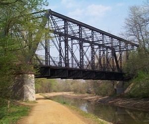
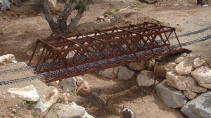
I had envisioned a very common warren truss steel bridge, but when I saw this whipple truss it gave me the idea for a hanging A truss. The whipple would have been cool but space does not allow for the long lines that would be required.
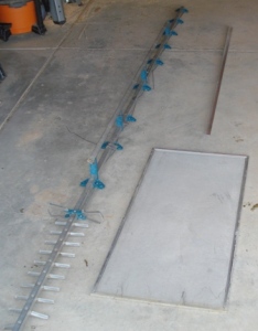
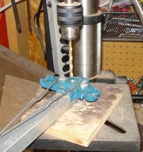
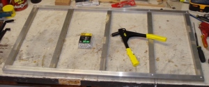
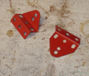
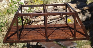
This project will be mostly aluminum as I need to pop-rivet it together and make a lot of cuts using a hacksaw. For materials I have the center support of an old TV antenna, several window screen frames and the left over ceiling hanger wire from the Quadrangular bridge project. Items I purchased are a length of 1″ X 6′ aluminum angle stock and four dozen bolt plates from an old erector set. I started by drilling out the rivets on the antenna so I could salvage the 1″ square tube.
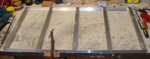
I cut the tubing into five 20″ lengths. This is long enough to allow both tracks to pass through the structure with adequate space between. The angle material was cut to three foot lengths for use on each side. Using 1/8 inch rivets I set a single pop-rivet at each joint, on what will be the bottom of the structure.
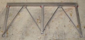
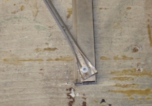
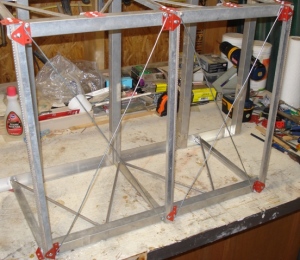
The side panels are laid out. Each one consists of a section of 1″ tube measured to 2.5 feet long, five pieces of the window screen frame, four pieces of the screen retainer and eight of the erector set plates. The horizontal and vertical pieces are attached from the front side. Attention was given to keeping the rivet pattern the same on matching structural joints. The side was then flipped over and the diagonal cross members were attached. Because the head of the pop-rivet setter is so large the screen retainer pieces had to be pried open and laid flat on each end. The center joint had to overlap both pieces. Once riveted the edges were bent up to cover the rivet head.
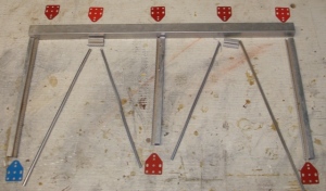
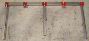
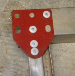
The sides were attached to the deck using the erector set plates. The horizontal members fit inside the angle material with the center support resting on top of the center cross brace. The top cross braces are made from lengths of the window screen frame laying flat. To hold them on, erector set plates were bent as shown. Screws were used to attach them. The first hole was drilled over-sized so the screw would not engage it and distort the frame.
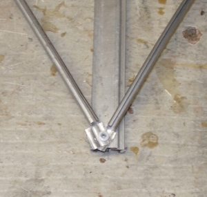
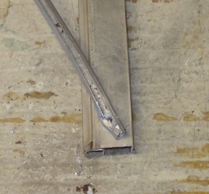
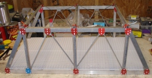
Aluminum hanger wire was stretched across the top of the bridge diagonally to help reinforce the structure. These were attached by wrapping them around metal screws at the base of each cross member. With the top done, end supports were cut from the 1″ tube to provide diagonal supports on the ends of the bridge. These are held in place by pop-rivets and erector set plates. The deck is cut from a plastic light louver. The kind used in suspended ceilings. It was cut down the middle in two pieces so it could be inserted and dropped into the center of the bridge.
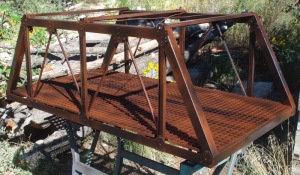
The bridge was painted with Krylon Black Industrial spray paint and adusting of oxide brown.
It looks pretty good and at less than $20 worth of materials I can’t complain. One of the reasons is the different sizes of the materials used and the fact that they are all standard industrial shapes. I do not think it would be as convincing if everything was made from the same size of material. Installation to come once I get the approach bridges built.
Double Track Steel Girder Bridges On The Mainline (Completed November 2015)
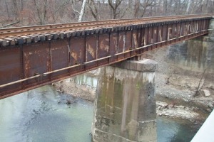
On each side of the A frame bridge are steel girder approach bridges. These are based on the general design of the single track bridge shown below. They are fairly simple with a few notable details that are typical of the real thing. The plates are riveted around the edges. Each panel is boxed in by the upper and lower top rails of the I-beam and separated by horizontal pieces of what would be L-channel.
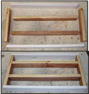
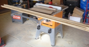
I want these to be durable without costing a fortune so I am using plastic to represent steel in the construction. The girders are styrene fascia boards. I ripped them to the correct height for the riveted panels and then cut them to length. The main support of the bridges is pressure treated pine. This is on the inside so it does not show. The rails of the I-beam and L channel are pieces of shower surround cut to width.
The width of the bridges was determined by the spacing of my double track. This distance varies across the layout but is always enough to allow the trains to pass each other with sufficient clearance. The length was determined by the fact that I could cut all four sides needed from a single piece of styrene. The frame is attached using drywall screws. These were recessed on each end of the styrene to allow the plate panels to lay flat over the screw heads.
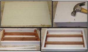
Once the frames were assembled I cut a solid piece of shower surround to cover the entire top. It over hangs about 1/4 inch to represent the top of the I-beam rail. I used a solid piece to keep rain and snow from getting to the wooden supports inside the bridge frame. The frame was laid on top of the panel and the supports traced onto it. It was them placed on top with these lines showing so I could attach it with ribbed panel nails centered in the supports.
One inch wide strips were then attached on the bottom of the supports also with 1/4″ overhang. These represent the bottom rail of the I-beam. I went all the way across the ends with the strips flush with no overhang. This will give the end of the bridge support on the pylons and abutments.
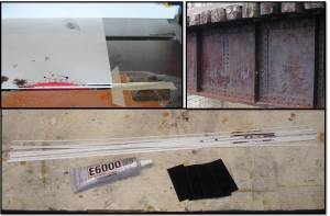
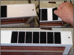
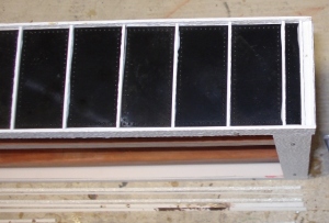
To make the L-channel dividers between the panels I cut 3/16″ strips from the surround. These were then cut to length and sanded as needed. To make the riveted sides I bought several dozen of the riveted panels sold on E-bay for converting a HLW engine cab from a wood side to a steel side. I started in the middle of the bridge with a divider piece and worked my way to the end. Everything is held together with E6K white. It was all I could find at the store and I do not believe there is any difference other than color between the various E6K products. GOOP would also work.
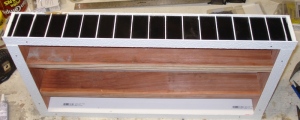
Working down the side I squeezed out a few lines of the glue then spread it smoothly with one of the panels. I alternated between one of the divider pieces on edge and a rivet panel until I reached the last full space. I then cut a panel down so that I could finish the end with a horizontal divider on edge, then one flat and then one on edge again. It looks pretty good.
With both sides done I covered the deck in wooden bridge ties. These overhang the sides of the bridge by 3/8″ and are attached using ribbed panel nails through the deck cover and into the wooden supports on the inside. As it turns out their heads were covered by the wooden guard rails.
Both bridges were painted with a high quality enamel spray paint for engines and marine use. I wanted something that I hope will stick in the extreme weather of New Mexico. We will find out. The wooden ties were painted with Krylon brush-on enamel barn paint and everything was weathered with red oxide and flat black spray paints.
To complete this bridge project I have to install all three on the layout. Ughh…more dirt and rocks. Here is where they go on the south end of the layout.
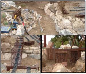
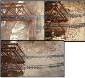
I began by removing the tracks on the main line along with the existing trestle sections. Next the dirt was shoveled out of the way. The steel deck bridges are much thicker than the trestle decks so the temporary abutments had to be adjusted on each end of the span. These will be used for now. Hopefully next year I will make concrete abutments and piers for these bridges to rest on.
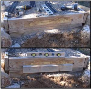
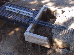
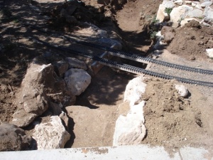
I started on the left side as this is the end of a curve and the abutment could not be moved back any further. Not that it needed to as the bridge run is slightly shorter then the trestle was. You can see how far the right abutment had to be brought out to close the gap. In the middle the bridges are supported by pieces of pressure treated wood. Everything is leveled up. This is a vast improvement as the original trestles were put in in a rush and had sank about 1/2″ in the middle creating a low spot in the track.
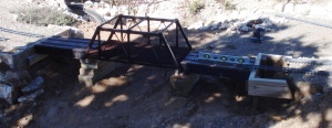
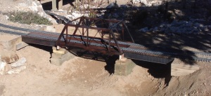
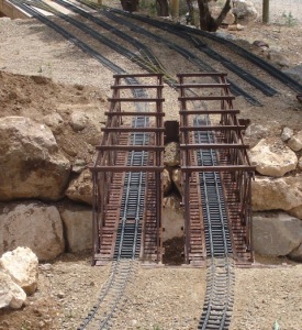
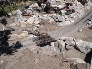
Here is the bridge group all finished. The space under the girder bridge will eventually be modeled as the road into the town of Broken Wheel. The trestles will become part of Ohmigawd trestle while the dirt that was removed finished leveling the town site on the backside of this picture.
Queen Post Pony Truss Bridge Pair On The Mainline (Built but not installed May 2015)
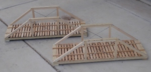
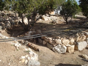
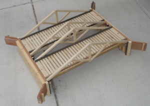
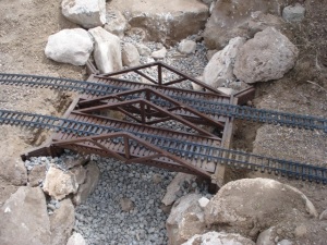
The queen post bridge pair spans the North end of Cibola Arroyo. They are 23 inches long so some trestle work will have to be done to narrow the gap shown in the picture below. I built these as a class for the NMGRR summer “How to Program”. I do not want to be sidetracked from the Year Of Track project so they will have to wait for installation. For now the track is supported by temporary bridges in the form of 1 X 4 cedar pickets. Construction is the same as my other bridges with two pieces of 1/2″ conduit held captive between the support beams. The truss parts are 1/2″ beams ripped down from pressure treated pine. Unlike the King post bridge which has only the single vertical beam the Queen post bridge can have any number of these sections. This bridge type is different in its load bearing qualities from what you might expect. The diagonal and horizontal beams are compression pieces while the upright vertical beams are under tension.
The tension rods crossed diagonally are for lateral loading. Most Queen post bridges would also have a crossbeam under each vertical beam with diagonal supports to prevent the truss from deforming sideways under load. Not all bridges of this type have them but they are a nice detail. I unfortunately do not have the room since this pair will be installed parallel to each other. Below is a steel version of a queen post bridge and a still standing covered version.
The completed bridges with some Ozark Miniatures details for looks. They will get painted brown next time I have a paint can open.
Quadrangular Warren Through Truss Bridge Pair On The Mainline (completed April 2015)
Here is the section of track I am working on. I removed the high trestles and extended the ground to accommodate some changes in the yard at Cibola. The branchline will pass under the main next to the arroyo. The bridges will have to be just over 6′ to cross the span.
This was supposed to be a pair of Howe Truss bridges but it appears that I am not building Howe Truss bridges despite what they look like. My train buddy Devon Sinsley started a very good discussion on LSC as to what makes a Howe Truss bridge, a Howe Truss bridge. You can see his research and the comments of several excellent modelers on the subject here: http://www.largescalecentral.com/forums/topic/23504/howe-truss-design
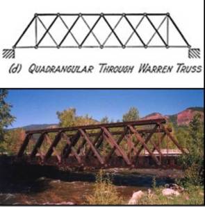
So what am I building? It would appear to be a through truss version of a Quadrangular Warren Truss bridge similar to this pony over the Hermosa creek.
To begin I built new abutments as the temporary ones I had used were not even a good starting point. These are made using pressure treated pine and some cedar scale lumber. Measurements were made for all of the supports, then a brace was added on the back to prevent warping. I used drywall screws and TB3 to hold it in place. Supports, sway braces and faux cribbing complete the look. To finish, the abutments got a coat of Rustoleum brown paint. I did not do wing walls on this pair since there will be plenty of rocks holding them and the ground in place.
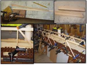
Bridge construction began by ripping various sizes and lengths of pressure treated pine. For strength, and to prevent warping, I have incorporated two lengths of 3/4″ ID pipe into the bridge frame. The bridges measure 74″ long and I did not feel the 1/2″ conduit would be strong enough.
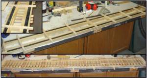
Supports are glued on both ends. Cross beams are run underneath and decking across the top. I made it 1/4″ thick. I don’t know why. It should have been three times that but it is a done deal now. For this bridge I included some wooden guides to hold the track in the center of the bridge so it would not move during expansion. Clearance tolerances are close on the interior (7.5″ across and 10″ high) and I do not want to snag a car or engine on the bridge interior. Once both decks were dry I added panel nails and pin nails where needed. Both decks were painted with Rustoleum brown as painting them after final assembly would have been a bear.
While the paint dried I cut the truss and overhead cross beams. The first two rows were glued in place and then painted. Once the outside row of truss supports along with the top and bottom beams are on there will be no practical way to paint between them. Clamps clamps and more clamps. I used every large clamp I own in assembling the trusses. To insure that the height is uniform I used a pair of 90 degree clamps to hold the upper beams in place using a temporary spacer. Once both bridges had their trusses in place I painted those parts brown along with all of the loose pieces for the final row of supports and beams. While they dried I made the tension rods.
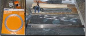
The rods are made from drop ceiling steel hanger wire. I got a roll of 100 feet and cut lengths of 14″. They are not perfectly straight but the material was very cheap. Hexagonal nuts were threaded on the ends and then everything went and got a coat of black spray paint. Being steel they will eventually rust and look pretty good.
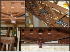
All of the final parts were glued into place using TB3. Pilot holes were drilled in the side of the lower beams across all the supports and into the inner beam just above each of the cross beams. I then drove a 1.5″ ribbed panel nail in. You can see in the picture how they are off center to allow the tension rod to pass along the center line of the upper and lower cross beams. The same thing was done to the upper beams but I used pin nails since the top was to thin to take lateral hammering. The upper cross beams were attached using TB3 and .75″ ribbed panel nails driven down through the top of the outside truss support.
To install the tension rods I drilled holes through the center of the top cross beams passing through the top of the middle truss support. I flipped the bridge upside down to drill the holes in the bottom cross beams. With the bridge upright once again a small amount of E3K Black was placed in the lower holes. The tension rods were given a washer and then passed through the upper hole and guided to the lower hole. Before sliding them down completely I put a little E3K under the washer and upper nut. To finish I gave each rod a gob of E3K at the base where they passed through the lower part of the truss supports.
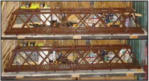
Some touch up paint and both bridges were complete. I think I have about 30 hours in each one. Looks like I need a hobby because this job is working me to death.
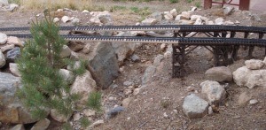
Now that the bridges were done it was time for installation. I removed the track that was hanging across the open span and dug out the rocks and dirt on each side of Cibola Arroyo to allow the new abutments to go in. I attached the first bridge using a 2″ drywall screw through the end of the deck and into the cross beam of the abutment below. This was repeated on the other end. I was very happy that the bridge dropped into the mounting area on the abutments without any issues. To line everything up I loosely laid the track in place. Some pushing and shoving was required but less than I expected. I installed the second bridge in the same manner as the first. Using bricks, rocks and wood pieces I leveled and squared the bridges with the track. Once everything was in place the rock walls of the arroyo were rebuilt and the track connected.
One last check for alignment and then I back-filled the area behind the abutments with gravel and sand. To finish, crusher fines were used to ballast the track.
Well it only took me four years to work up the enthusiasm to build these bridges but here they are. I am very happy to be done with this job, at least the trains will look good rolling across them.
King Post Bridge Pair On The Mainline (Completed 2014)
Here is how it looked in the beginning. Very utilitarian. In conjunction with building this bridge I also made major progress on the scenery in the Southeast corner of the layout.
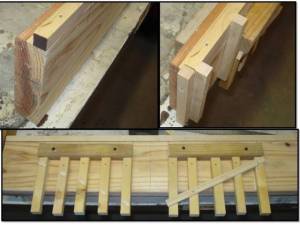
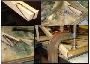
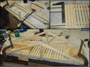
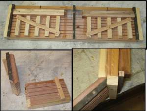
I began construction of the bridge by assembling the main beams. you can see in the pictures where the conduit was hidden inside. In the future I will spray paint these black before assembly to help hide them. They are hard to paint once everything is together. The A frames were added next. I had to cut out these notches to make them rest on the bridge beams properly. I could have placed them on the sides but it narrowed the gap between the tracks to much. The correct position would have been on top of the frame to take the horizontal load but then the connie would not have fit between them.
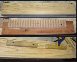
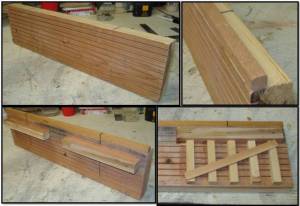
Next I decked the bridge with 1/4 ” by 1/2″ strips in a spaced pattern. This provides great support while giving the bridge a pleasing look of frailty. The abutments are made from 1 x 4″ cedar with 1/8″ grooves cut into them on the table saw to represent individual boards.
The wing walls are made the same way. I also cut a 45 degree miter on opposing ends so they would butt into the corners at each end. The bridge is assembled and pilot holes for dry wall screws are made in the center of each bridge end to attach it to the support below. This keeps the everything migrating out of position with the frost heave. It also allows me to remove a single bridge after installation without disturbing the abutment. Now everything gets painted on all sides.
Installation is accomplished by removing the necessary track sections digging out sufficient fill for the bridge and abutments to sit freely and then supporting rocks placed underneath to hold it at a level height. The track is reinstalled and the bridge is raised or lowered to match it. This is easy to do on these short spans, not so much on the long ones. Large gravel is used to fill the areas behind the abutments along with engineer fill. This will help drain water away from the wood and hopefully extend the life of the bridge.
For completion ballast, gray crusher fines, are poured on and swept clear of the ties. Finally rail traffic resumes.
The foreman says “job’s a good’un” and tells the boys to enjoy their weekend. MOW never ends on the Cibola.
Pratt Truss Bridge for the Albuquerque Botanical Garden (completed 2013)
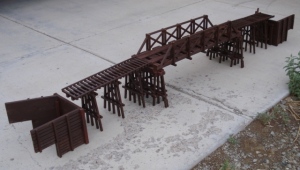
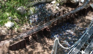
To get my skills warmed up I first built and installed a new Pratt Truss bridge for the Albuquerque Botanical Garden in 2013. I dubbed it the “Frankenbridge” because it was so ugly only it’s creator could love it. They were glad to get it and I was glad to have the opportunity to refine my technique. Here it is just before installation and after installation in the park. This is a heavy water zone and is damp most of the time. It replaced a Bridge Masters model that lasted almost 15 years. When we dug it up everything below the soil line had rotted away.
I do not claim to be a scale model bridge engineer. I build my bridges for strength and durability. The two biggest problems they face is warping, usually in the form of sagging, or decay. To prevent the warping I use well seasoned pine and or cedar. I also incorporate two lengths of 1/2″ metal conduit into the frame. For assembly I use Tight Bond 3 in every joint and either drywall screws, ribbed paneling nails or pin nails, whichever is required and most feasible for the need and the size of the wood members being joined. Dimensions for 1/20.3 scale are (length required) x 7 1/2 – 9 inches wide (7 1/2 inch inside clearance) x 3-6 inches for open truss or 10 inches for through truss.This clears all of my trains, of which the shay with the diamond stack is the tallest.
For rot I try to use pressure treated pine for the abutments and the main beams and then give everything a thick coat of dark brown Rustoleum oil based paint. I know a lot of people like the look of natural wood but I do not want to have to seal my bridges once or twice a year. A little gray and black spray paint does a good job of weathering them. So far I have had no failures, but they are young bridges.
I run my track over the top of the bridge instead of spiking it down. Spiking looks better but with temperature swings of 50 – 60 degrees between the low and high every day in the spring and fall I have a problem with snaking from expansion. Running it over the top eliminates that issue making track maintenance much easier on my back and knees.








You must be logged in to post a comment.